|
|
|
Note: This document is a continuation of
Understanding Early Street Light Circuits
The challenge that engineers faced with early street lighting systems involved getting the appropriate current to travel long distances without suffering excessive line loss or having to use impractically large diameter conductors. The answer lay in connecting the lamps in series, daisy-chaining one lamp to the other, creating a large loop. If each lamp individually required around 50 volts to operate, a string of 40 lamps would require 2,000 volts. The amperage required would not increase substantially so the system could run on a high voltage, low amperage basis, needing much smaller conductors to supply the lights. Since the lamps were daisy-chained together, if one lamp failed, the whole circuit would go dark. This problem was initially addressed by isolating each lamp with an autotransformer. The series circuit would feed through the autotransformer and the autotransformer then fed power to the lamp. If a lamp failed, the load on the circuit would change but the remaining lamps would remain lit. Some means of regulating current on the circuit was necessary to prevent remaining lamps from getting too much voltage as other lamps failed and dropped out of the circuit. |
|
|
The answer to the failed lamp problem was solved by means of the constant current regulator.
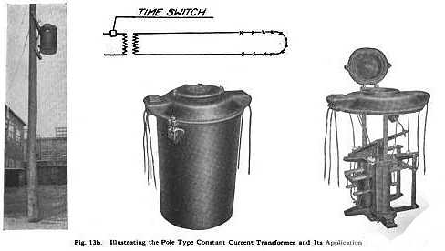
Most regulators ran at 6.6 amperes. Some higher intensity circuits operated at 15 and 20 amperes. Voltage supplied would be in the kilovolt range, however the voltage provided to the lamp circuit would vary according to the number of operating lamps in the circuit at any given time. Four types of series circuits were in common use. One was called an "open loop" circuit. In this circuit a single conductor ran the entire loop of lamps and returned to the regulator. The open loop design was the most economical as it required the least amount of conductor cable. Figure 1 illustrates a basic open loop circuit. The regulator is supplied by high tension service. A time clock, photocontrol, or in some really old systems, a manual switch operating at 110 volts would activate an oil switch that powered the regulator. The regulator then provided a constant current, usually 6.6 amperes, and adjusted the voltage according to the number of lamps operating in the circuit
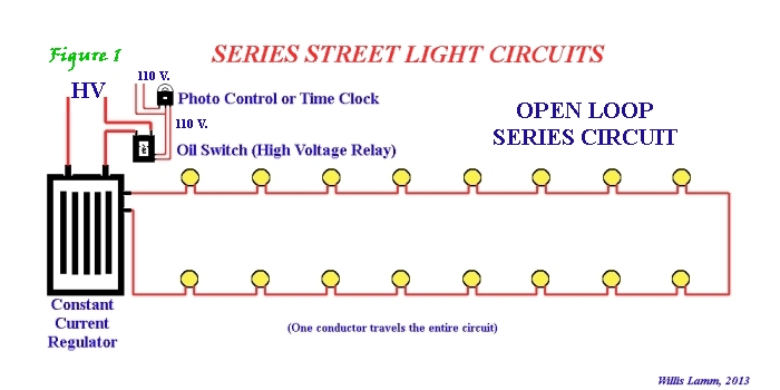
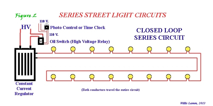
Figure 2 illustrates a circuit called a "closed loop." In this circuit both conductors from the regulator traveled the entire circuit. This design increased the cost of wiring however it did provide an advantage that if part of the circuit failed, the two conductors could be shunted (jumpered) together prior to the failure in order to keep the remaining lamps operating.
Most utilities utilized a combination of the two types, running an open loop down primary streets with shorter closed loops branching off onto side streets. Figure 3 illustrates this combination.

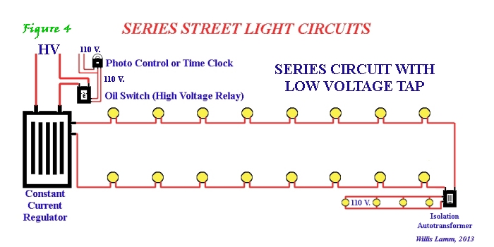
As illustrated in Figure 4, inventors even designed a means to provide lower intensity lighting for alleys, traffic beacons and similar uses by installing autotransformers that would provide appropriate voltages to those special branch circuits. Typically these branch circuits fed from the high tension series circuit operated at conventional line voltage.
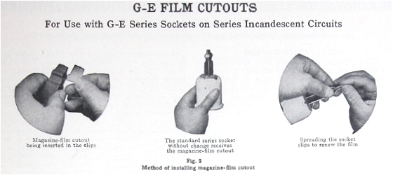
Since series circuits were basically one great loop of lamps, technology had to be developed to prevent the string from going dark if a lamp failed. Specific discussion on this aspect appears in Understanding Shunts.
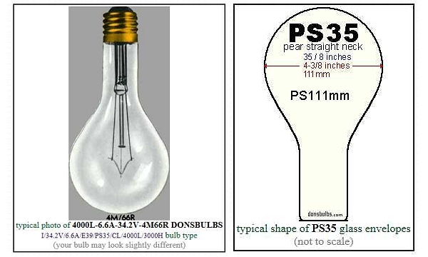
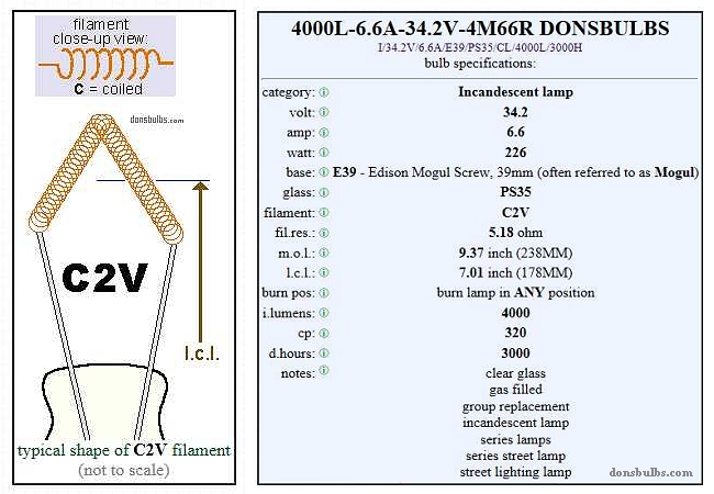
Typical 4000 lumen series circuit incandescent lamp bulb.
|
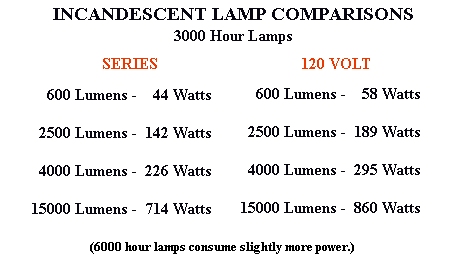 As primitive as they appear to us today, well engineered series circuits actually provided more light per watt consumed than conventional line voltage lamps. As technology developed, these circuits transitioned from serving arc lamps to 6.6 ampere incandescent lamps and ultimately 6.6 ampere mercury vapor lamps. Many of these circuits are still in service today. In Detroit, for example, some of the circuits are still turned on by hand at the end of each day at a central station.