Street Light Technical Information
|
|
Street Light Information Sheet - Understanding Multiple Circuits |
|
Note: This document is a continuation of
Understanding Early Street Light Circuits
While series circuits were the predominate street light design, acquiring a regulator and related equipment for smaller clusters of lamps was prohibitively expensive. However providing comparatively bulky and expensive early photoelectric controls for individual luminaires was still not practical. Several lamps still needed to be controlled from a central point. For those situations, multiple circuits were utilized. In multiple circuits the lamps operated at line voltage, typically at 110 or 220 volts. A single manual switch, time switch or photocontrol operated the circuit. Generally speaking there were two types of multiple circuits that were commonly used. The simple multiple circuit had a central control point from which dedicated conductors ran in various directions as far as was practical due to line loss associated with low voltage circuits. Therefore the number of lamps that could be operated in such a circuit was limited by distance, however this circuit worked well when lamps were relatively close together. Figure 5 illustrates this simple circuit.

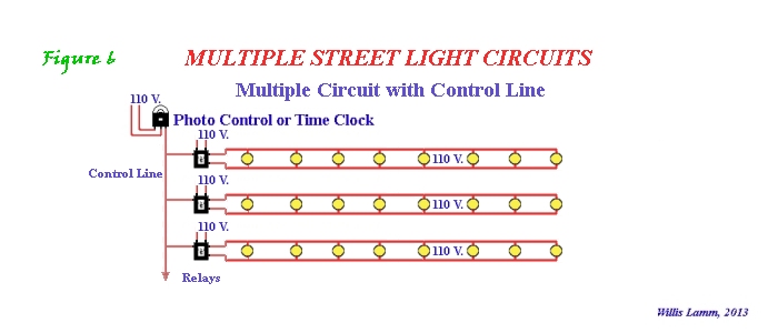
In order to expand the range of the multiple circuit, a control line was strung from the switch to more distant locations, or multiple control lines were strung in multiple directions. The control line would operate relays that were connected to their own sources of power and would operate small groups of lamps. Relays consumed small amounts of power so a control line could run for miles serving several groups of lamps without suffering significant line loss. Some systems simply ran control lines from the switch as illustrated in Figure 6 or they might be piggybacked onto simple multiple circuits as a means to extend lamp control beyond the practical limits of the simple circuit.
This kind of circuit was feasible since the various luminaires would be powered by conventional line circuits that supplied buildings and such, and were powered by the various transformers that supplied those circuits. They were simply operated by means of the control circuit. Therefore a lamp that received its supply separate from other lamps in the control circuit could then feed a small sub-circuit without affecting the other lamps in the same control circuit. Later as photocontrols became more compact, more reliable and more affordable, many newly installed street lamps were individually controlled. 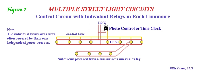
Additional References
|