In the 1800s photoelectric controls had not been invented, so strings of lights had to either be turned on manually or by time switches.
Since most large lighting circuits were run in series, many utilities supplied them from dedicated dynamos that were started at dusk and shut down at dawn. However this option required all of the lighting circuits to originate from the utility's "central station" or generating plant.
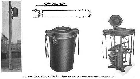
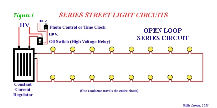
For circuits distant from a central station, series street lights were generally powered from high tension primary circuits. In those installations, current to the street lights would be supplied by a constant current regulating transformer (generally referred to simply as a "regulator.") The voltage needed to operate a series circuit would vary based on the number of lamps operating in the circuit.
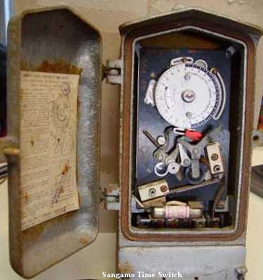
The regulator constantly adjusted the circuit voltage based on the number of lamps that were working. Such circuits could be turned on and off be means of a manual switch, by a time clock or by a control wire that ran to the regulator from a central station. These controls would in turn operate a high voltage relay called an oil switch that switched power on and off to the regulator.
A serious technical issue with series circuits was that since the lamps were daisy-chained together, if one lamp failed the entire string would go dark. To resolve this problem, autotransformers or cutouts were used to automatically bypass failed lamps and keep the circuit flowing.
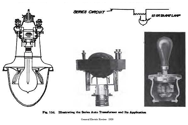
For a complete discussion on the various shunt transformers and cutouts used on series circuits, please see Understanding Shunts.
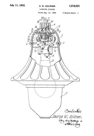 For smaller groups of lamps that did not justify the expense of a constant current regulator, lower voltage "multiple" circuit systems were often employed. Since only a few lamps could be powered from a single low voltage source, control circuits were added where large numbers of lamps could be controlled by a single switch, but the individual lamps or small groups of lamps would be powered locally and were operated by means of relays. Early relays were pole mounted. Later designs included relays built into the luminaires themselves.
Multiple circuits could also be daisy chained to spread the load over more transformers. An initial group of lamps fed by one local transformer would be controlled by a switch or clock, or perhaps later by a photocontrol, and a "control lead" would extend from that group to a relay that controlled another group of lamps supplied by another local transformer. A control lead from that group could then extend to yet another group, and so forth.
Ultimately series type circuits were found to be more efficient overall and actually produced more lumens of light per watt consumed, so multiple circuits were far less frequently used.
| 
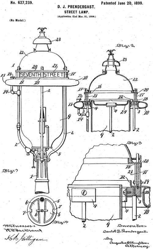
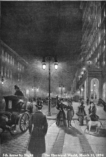
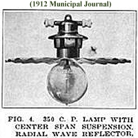
 Thomas Edison designed the first practical incandescent lamp in 1878, however the amount of light produced by his early carbon filament lamps was far less than that produced by arc lamps. Nonetheless Edison lamps did find their way onto many streets, often on relatively short posts in clusters of lamps on narrower residential streets where less lighting was needed and the harsh intensity of arc lamps was less desirable.