Part Two
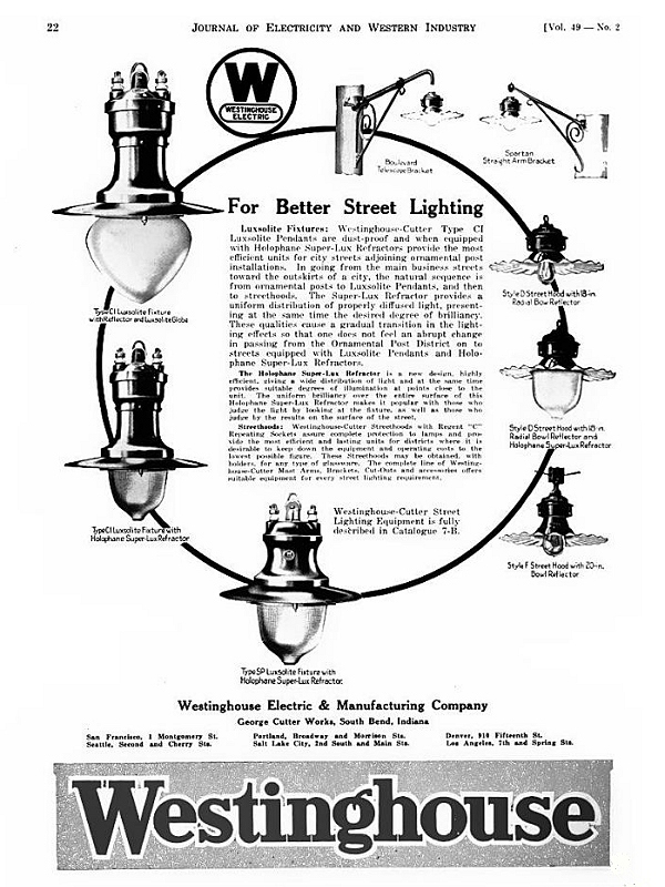
This document is a continuation from Part One Early street light globes generally were either frosted glass or rippled glass. The objects of those designs were to diffuse the light and visually provide a larger light source than the lamp's filament. Those designs could not materially redirect the direction of the light. There were early experiments in redirecting he light through the use of tiny prismatic facets inside glas globes. The earliest were used for indoor lighting, however it soon became evident that these principles could be used to improve street lighting. In 1915, Otis Mygatt designed the dual prismatic refractor. The concept seemed simple enough. Two separate glass globes were fitted together, one inside the other. One globe had vertical facets while the other had horizontal facets. The result was an incredibly useful light and Mygatt's design is still used today by Holophane Lighting in very high-end luminaires.
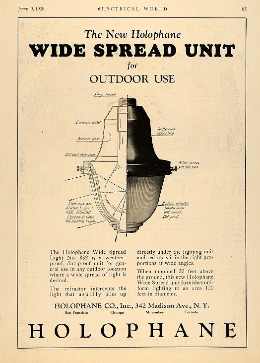
From that point on, designers generally followed two paths. One involved ripple glass diffusing globes where light was directed by means of metal deflectors placed inside the luminaire and the other involved prismatic globes where light was directed by means of prismatic facets inside the globe. Prismatic globes had the advantage of actually increasing light intensity in directions desired while decreasing intensity toward, for example, houses. However lamps had to be properly placed in these luminaires in order for the prismatic globes to function properly. As a result, adjustable sockets and sighting marks were employed to produce the best light pattern for each type of globe and lamp bulb combination. (Examples of how sockets would be adjusted to achieve proper lamp position can be seen in the feature, Adjusting a Street Light Socket Using a Rolph Sighting Mark.) Estimating dates of older luminaires. For purposes of dating street lights, prior to World War II metal clad high voltage series suspension type luminaires typically required large bodies similar to the GE Form 6 (see Part One.) More compact luminaires were manufactured with ceramic bodies to prevent high voltage arcing during wet weather or if the conductors swung against a luminaire in high winds. Series circuits also had to be protected with shunting devices so that the string would stay lit if a bulb burned out. The very early high voltage series street lights had auto transformers to isolate the bulbs from the circuit, often mounted inside the larger bodied luminaires. In the early 1900s various automatic cutouts were employed that were more efficient and less bulky than autotransformers. (For a complete discussion on autotransformers and cutouts, please visit Understanding Shunts.) Designs such as the Thomson and Jones film cutout sockets came into use. In these designs, when a lamp failed, the series voltage (typically less than 50 volts across the lamp bulb) would go high (often over 2,000 volts.) An arc would shoot across the cutout's insulating film, which then would melt and created a path around the failed bulb. (Additional information is available in the feature, Street Light History.) Early street lights that had conventional mogul lamp sockets, as opposed to Thomson or Jones sockets, would have typically been used for low voltage (110 - 220 volt) applications. How these facts are important for dating early street lights are as follows. Autotransformers were being phased out by the 1920s when film cutouts were being adopted by manufacturers. Glazed ceramic bodies allowed for a more compact design, acted as insulators for high voltage series circuits, and were the most commonly used for externally wired fixtures. Metal bodies were not typically used for externally supplied high voltage circuits due to the limited insulation provided by fabric coated wire. |
1930s GE high voltage series street light.
|
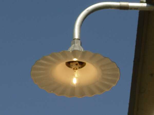
Comparable low voltage street light with conventional socket.
|

| For a several years GE produced a ceramic bodied luminaire that was convertible for either high voltage or low voltage circuits. This lamp had two entrances and two sets of lugs, allowing for exterior connections for high voltage circuits or "through the arm" interior connections for low voltage supply. Wooden plugs closed the unused entrance holes. |
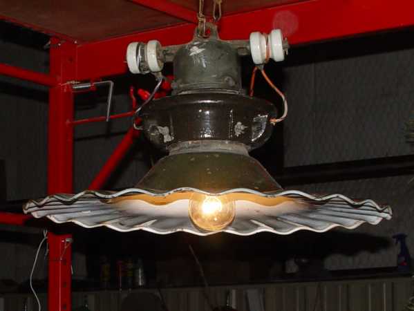
1920s GE "dual service" radial wave street light.
|
Wooden plugs closing the low voltage entrances.
|

|
World War II produced better insulation technology. However before that time it was a safe bet that a pre-war high voltage street light had a ceramic body, and that a fairly compact luminaire with a galvanized iron or aluminum body would have a conventional low voltage socket in order to be a pre-war lamp.
In 1941 a new design was being adopted that eventually became known as the NEMA "latch-on" design. NEMA specification Luminaires all had the same opening size where reflectors mated to the luminaire bodies and a standardized latching system. This design allowed for interchangeability of reflectors and refractors without having to remove and install new luminaire fixtures. These bodies had the ability to be supplied by either low voltage or high voltage circuits as the entrances of various designs could be bolted onto the bodies, or blank plates installed if the lamp had "through the bracket arm" wiring. |
NEMA fixture with outside lugs for older fabric coated wire.
|
Entrance for plastic coated wire (with internal lugs.)
|
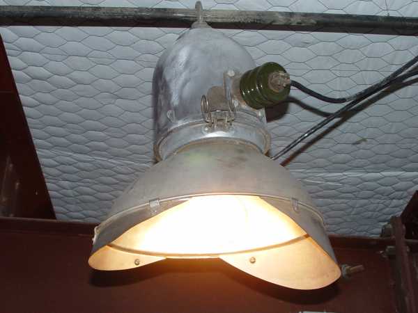
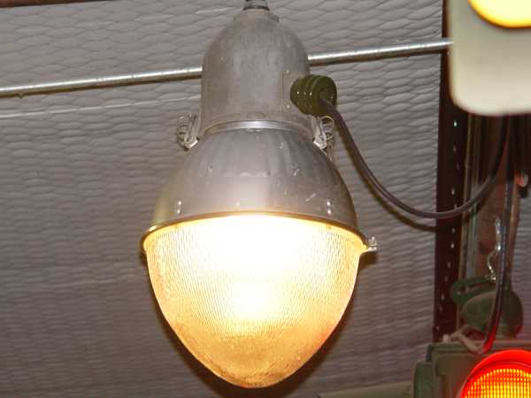
Typical pre-war luminaires.
|