Street Light Technical Information
|
|
Adjusting a Street Light Socket Using the Rolph Sighting Mark |
|
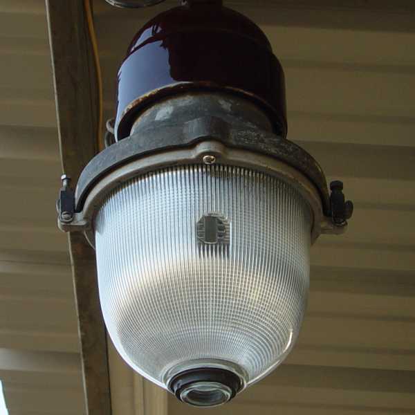
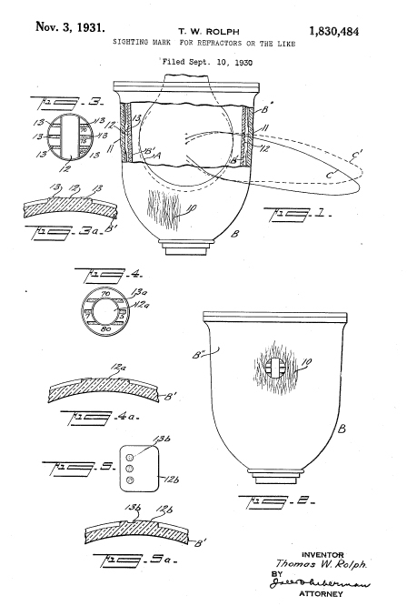
"Wide Spread dual prismatic refractors were generally designed to produce maximum illumination in an area of about 75 degrees from a vertical line under the street light. However that pattern required that the filament of the bulb be in the proper location within the refractor. Early bulbs were similar but the actual distance from the filament to the base of various bulbs could vary slightly. Furthermore the dual prismatic refractors had the ability to cast either a wider or narrower peak light pattern depending on the position of the bulb. The higher the bulb, the narrower the pattern. The lower the bulb, the wider the pattern - up to about 80 degrees from vertical. To provide more accurate light patterns, manufacturers would provide lamp sockets that could be adjusted vertically. Thomas Rolph designed a sighting mark which was basically a window where the lamp filament could be spotted and aligned with certain indications associated with Rolph's sighting mark. Drawing of Thomas Rolph's Sighting Mark. |
| Adjusting the Socket |
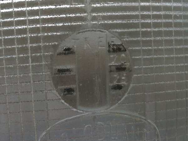
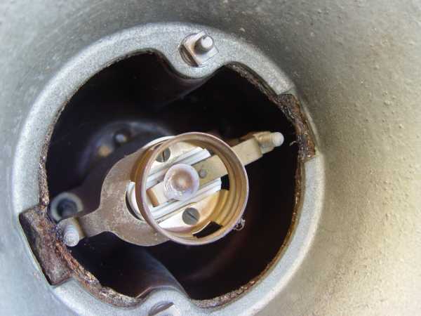
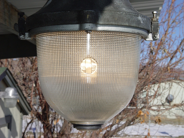
View of the sighting window and sighting marks.
 GE
GE
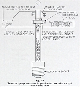
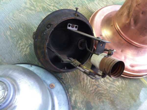
GE luminaires had internally adjusted sockets. Adjusting a socket required the lineman getting his hands on uninsulated conducting hardware. GE developed an adjusting gauge that would screw in the lamp socket so the socket could be properly signted in with the power off.
Without this gauge we have to view the filament through the sighting window and estimate the distance that the socket needed to be adjusted, power the lamp off, remove the body and refractor, loosen the mounting screw and make the adjustment. Then it was time to to reinstall the body and refractor, repower the lamp and check the adjustment through the sighting window.
View of GE's adjustable socket.
|
|
Holphane
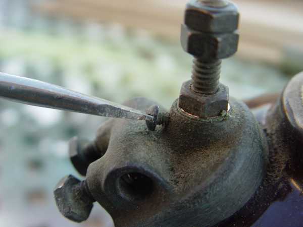
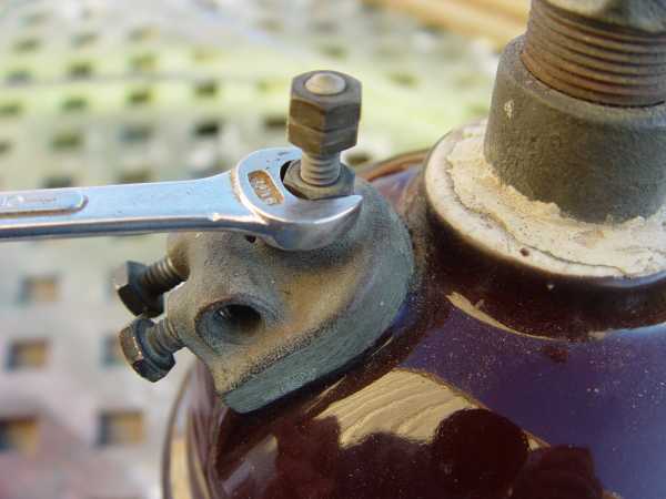
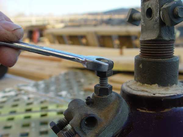
Many early Holophane lumninaires came with externally adjustable sockets so that the lamp position could be checked as the socket was being adjusted. The following procedures describe adjusting a Holophane socket. Please note that the socket adjusters are connected to the conductor binding posts and therefore they are part of the electrical circuit. These sockets should not be adjusted unless power is disconnected! View of the socket suspended from two threaded adjusting stems.
|

Return to
Holophane No. 432 "Wide Spread" Street Light