Willis Lamm's
|
|
OLD TIMEY TRAFFIC SIGNAL SEQUENCES |
I grew up in an age when some really funky signal sequences were pretty common. There were basically two common types of controllers back then, what we called "ratchet cam" and "die cut." We distinguished between the two since both types were electromechanical.
Ratchet cam controllers had cams that could be configured in the field and were commonly found in traditional pedestal or pole mounted controller cabinets. Die cut, or Synchron controllers were a series of simple die cut cam lobes held onto a common shaft and turned slowly by a small clock or timer motor. These were most commonly found in the bases of self contained 4-way signals although they were occasionally to be found in small pedestal or pole mounted cabinets when used to power multiple heads.
Ratchet cams were turned by a ratched solenoid that quickly advanced the controller camshaft a specific distance each time a clock key called for a display change. The movement was so swift that minor faults in the cam shaping were virtually unnoticed. Die cut controllers produced "warts and all" displays since the cams turned slowly, usually at a constant 1-RPM. If any cam face was slightly untrue, the color it controlled might stay on a little too long or went dark a little too soon, and that's the way the signal displayed.
Actual videos of these sequences are viewable from the YouTube links that appear on this page. Anyone interested in posting additional links to old signal sequence videos is welcome to add to this information base.
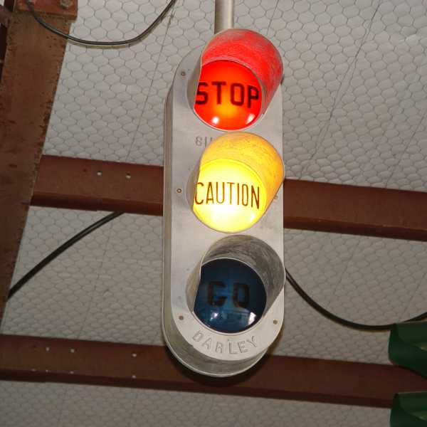
| Two-Color Signals |
|
Two color signals had no yellow light section. The signals typically displayed green, then either a short "dark" interval before displaying red, or red overlapped the green display for about 3 seconds before the signal went to red. The sequence in the video is a reproduction of the overlap sequence used by 2-color signals in Daytona Beach, FL in the 1950s and 60s.
View the video sequence on YouTube. |
|
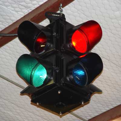
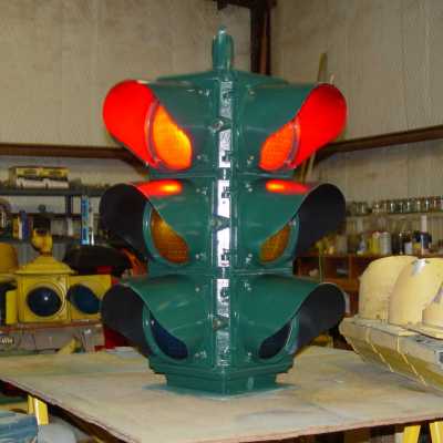
| Darley Three Bulb Sequence |
|
This is one of the earliest electric three color traffic signal designs, based on William Potts' original three color traffic signal design used in Detroit. The entire signal uses only three bulbs, and each bulb sends light in all four directions. The sequence had to allow yellow lights whether the signal was turning red or green since, for example, if the main street was turning red, the cross street was turning green. Back in those days a yellow indication basically meant "caution" as the light was changing. As you can see from the video the yellow light comes on for a few seconds as a warning, then goes out, then the light changes. View the sequence video on YouTube. |
|
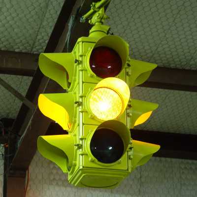
| All Yellow Interval |
|
For the most part the introduction of the yellow section was to convey three meanings. It projected "Caution" since the movement in the intersection changing directions. It said, "Attention, the signal is changing" so drivers at red lights could get their old timey stickshifts engaged. It also warned pedestrians in crosswalks who could only view the cross street side of a center mounted signal the light was changing and that green for opposing traffic would soon follow.
Older traffic regulations placed more responsibilities on drivers. For example, drivers were not to enter an intersection on a yellow light unless it was unsafe to stop. Thus a signal that displayed a yellow light to drivers already standing at a red light meant the same as the red light. They had to wait for green before proceeding into the intersection. (I met a retired Illinois cop who mused how the Chicago Police loved to ticket unwitting drivers who entered intersections during all yellow intervals.) View the sequence video on YouTube. |
|
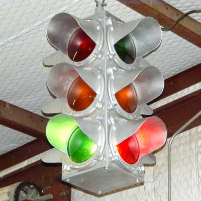
| Double Yellow Overlaps |
|
Originaly drivers would stop or go on red or green. Yellow sections were added to provide a warning that the light was changing. Some jurisdictions chose to have yellow displays overlap the red and green displays so there would be no confusion as to which way the light was changing. The yellow overlap from red to green would still give notice to stopped drivers to get their cars in gear and warn pedestrians who could only see the cross street side of the signal when in the middle of the crosswalk that the light was changing.
I was surprised to acquire a Crouse-Hinds Type M that came internally wired for a three circuit double yellow overlap. It must have been an early vintage Type M, or perhaps it replaced a damaged older three circuit signal. Since it was ready to light up, I wired it to a three circuit controller to display the double yellow overlap upon restoring it. View the sequence video on YouTube. |

|
| Darley Double Yellow Overlaps |
The classic Darley double overlap sequence, sometimes called the "stairstep sequence." was slightly different.
View the sequence video on YouTube. View the programming of the sequencer on YouTube. |
|
| Single Yellow Overlap |
|
Some jurisdictions didn't like the idea of a yellow display prior to a signal dropping to green. The theory was that motorists might tend to jump the green light. So some early sequences had yellow only overlapping green displays
This early Southern Autoflow has an internal die cut cam controller so the displays are a bit "sloppy" by today's standards. Again the yellow displays were primarily intended to catch the attention of motorists and you can see in the video that they aren't totally synchronized with the red and green displays. View the sequence video on YouTube. |

|
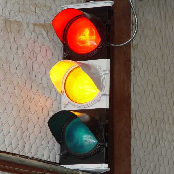
| All Red Interval |
|
In the 1950s a short all-red interval gained some popularity. The yellow display was becoming accepted as a "clearance interval" rather than a stop indication. The idea still remained that vehicles inside the intersection would have time to clear and approaching vehicles would stop during the yellow display. However drivers started to "push through" yellow lights and at larger intersections traffic getting a green light sometimes tended to move forward before all the cross traffic had cleared.
This Sargent-Sowell with an internal die cut cam controller is set to display short all red intervals. In addition, the cams in this later design internally controlled 4-way were more precisely cut and the displays are more correctly synchronized than in many earlier internally controlled signals. View the sequence video on YouTube. |
|
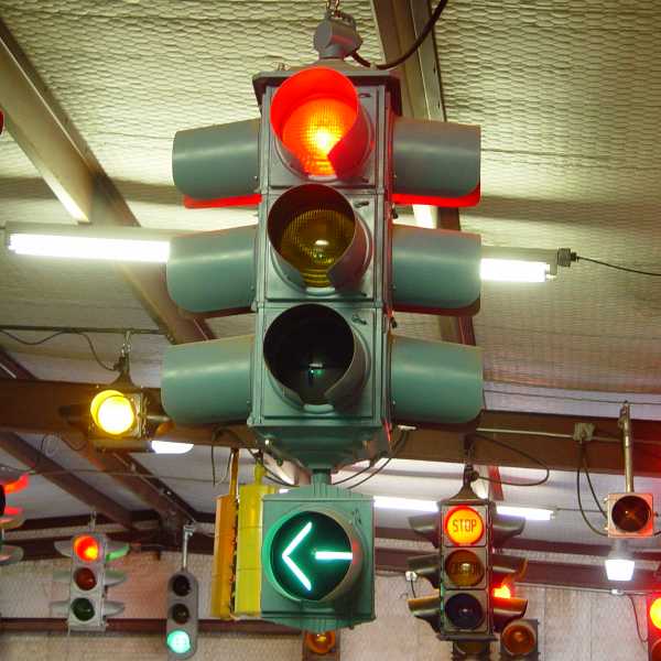
| Old Timey Protected Left Turns |
|
During the post WW-II automobile boom, many jurisdictions were finding traffic backlogged at intersections, often due to left turning vehicles that had to wait for oncoming traffic. Left turn pockets were added however vehicles still backed up at some intersections, blocking through traffic.
Short protected left turn intervals were added to traffic signals in some areas to allow a handful of vehicles in the left turn pocket to move out before through traffic received a green light and before pedestrians received a "WALK" indication. If the protected left turn was in only one direction, the left arrow might overlap the green ball. If opposing left turns were permitted, then the signal would display all red while the left turn arrows were lit. View the sequence video on YouTube. |
|
| UK (British) Signal Sequences |
| A number of automobiles in the UK still have manual stickshift transmissions and urban streets are quite crowded. As a result UK signals still display the old sequence where two seconds of yellow (amber) overlap the red display just before the signal turns green. The idea is to give notice to motorists to get their vehicles in gear as the light is changing. |
|
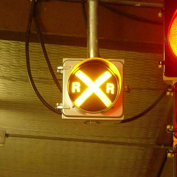
| Old Timey Railroad Preempts |
| Railroads were an important element in many early towns and it was not unusual for railroads and motor vehicles to share the same rights of way. Railroad tracks ran down the center of multi-lane streets and when traffic signals began to be installed, cars could not be held up at a red light if a train was rumbling down the street. Early railroad preempts are discussed on a separate page that also includes a video that illustrates a recreation of an early intersection that could be preempted by an approaching train. |
|